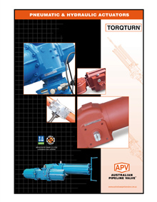
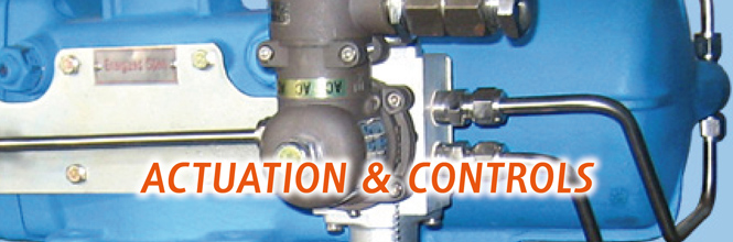
ACTUATION GLOSSARY
The following list of valve automation terms may help us
communicate and better serve your needs with our full in-house
engineering, automation, test & paint facility. This includes torque
testing up to 46,000 NM as well as submerged tank nitrogen testing.
GENERAL APPLICATION
TERMS
ON-OFF SERVICE
When the valve is being used to start
or cease flow by cycling to the full open
or full closed position.
MEDIA
The type of product flowing through the
valve.
MAXIMUM SHUT-OFF PRESSURE
The pressure of the media flowing into the valve against which the valve will have to close.
MODULATING SERVICE
When the valve is being used to throttle or regulate the flow rate by selecting varying positions between open and closed.
SERVICE TEMPERATURE
The maximum and minimum temperature of the media.
SUPPLY PRESSURE
The plant air supply pressure available to operate a pneumatic actuator.
STEM TORQUE
The force required at the valve stem to open or close the valve against system pressure and service conditions. Torque is expressed in Newton metres.
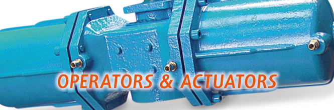
ACTUATOR TERMS
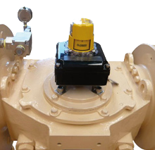
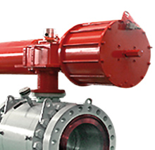
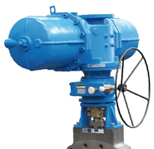
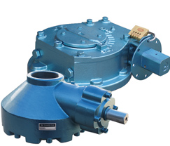
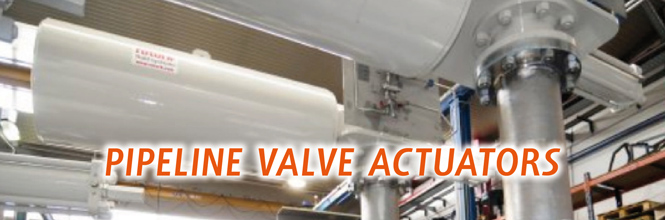
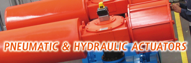
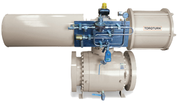
PNEUMATIC OR HYDRAULIC ACTUATOR
An air-operated or hydraulic operated mechanical device used to open and close or modulate a valve. The actuator, which is mounted to the valve and coupled to the stem, is designed to convert air or hydraulic pressure into mechanical force sufficient to operate the valve.
DOUBLE-ACTING PNEUMATIC OR HYDRAULIC ACTUATOR
Any pneumatic or hydraulic actuator which uses air or hydraulic pressure to drive the actuator output shaft in both the open and close direction. The air or hydraulic supply is piped to one side of a piston drive or a diaphragm while the air or hydraulic pressure contained on the opposing side is exhausted.
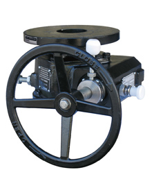
SPRING-RETURN PNEUMATIC ACTUATOR
Any pneumatic or hydraulic actuator which contains a single coil spring or group of coil springs to oppose the movement of a piston or diaphragm. As air or hydraulic pressure moves the piston or diaphragm the spring is compressed. When the air supply or hydraulic pressure is discontinued and exhausted, the spring extends and drives the piston or diaphragm in the opposite direction. This type of actuator is normally used for applications where it is necessary for the valve to move to the open or close position upon loss of air or hydraulic pressure supply, whether by design or by system failure.
FAIL-OPEN
A spring return pneumatic or hydraulic actuator is applied to the valve such that the spring will drive the valve to the open position upon loss of air or hydraulic pressure (may be termed “air-to-close”).
FAIL-CLOSED
A spring return pneumatic actuator is applied to the valve such that the spring will drive the valve to the close position upon loss of air or hydraulic pressure (may be termed “air-to-open”).
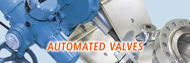
ELECTRIC ACTUATOR
An electro-mechanical device used to open, close or modulate a valve. The actuator operates the valve using an electric motor driving a gear train. While the basic function of the electric actuator is similar to the pneumatic, there are distinct differences in the application and flexibility of the two types, and these differences should be considered to select the proper type.
ELECTRIC FAIL SAFE ACTUATOR
Electrically driven actuator that contains an internal spring to close the valve on loss of electricity.
ACTUATOR ACCESSORY AND RATING TERMINOLOGY
NEMA RATING
National Electrical Code Ratings for electrical component enclosures.
NEMA 4 Weather-proof enclosure suitable for indoor/outdoor applications to protect from windblown dust, rain or hose-directed water.
NEMA 4X Offers the same protection as Nema 4 with the addition of corrosion resistance.
NEMA 6 Enclosure that may be submerged up to six feet for 30 minutes.
NEMA 7 Enclosure for hazardous locations, must be capable of withstanding an internal explosion of gases so as not to ignite an external gas-air mixture.
SIL RATING
SIL is an acronym for ‘Safety Integrity Level’. A SIL is a way of measuring the performance of a safety system, and/or the ‘Probability of Failure on Demand’ (PFD) for a SIF* or SIS**. There are four distinct integrity levels of SIL. The higher the ‘SIL level’, the lower the PFD for the system and the better the safety system performance. The higher the SIL level, the higher the costs and complexity of the system. A SIL level rating applies to an entire system. Individual semi components do not necessarily have a SIL rating but can be tested and certified for use as part of SIL systems. SIL levels are used when implementing a SIF to reduce an existing intolerable risk level to a tolerable process risk range.
* SIF is an acronym for ‘Safety Instrumented Function’. A SIF is designed to prevent or mitigate a hazardous event by taking a process design to a tolerable risk level. A SIF is composed of a combination of 3 elements: - logic solver(s), sensor(s) and ‘final element(s)’. A SIF always has an assigned ‘SIL level’ depending on the degree of risk that needs to be lowered. One or more SIF’s then comprise a SIS.
** SIS is a ‘Safety Instrumented System’. A SIS is designed to prevent or reduce hazardous events by taking the process to a safer state whenever predetermined conditions are violated. A SIS is composed of a combination of 3 elements: - logic solver(s), sensor(s), and ‘final element(s)’. Other common forms of SIS’s are ‘safety interlock systems’, ‘safety shutdown systems’ (SSD), and ‘emergency shutdown systems’ (ESD). A SIS can comprise of one or more Safety Instrumented Functions (SIF).
SIL 0 No safety requirement for the process function.
SIL A Risk reduction of less than a factor of 10 required from the process function.
SIL 1 Probability of ‘failure on demand’ between 10-1 to 10-2.
SIL 2 Probability of ‘failure on demand’ between 10-2 to 10-3.
SIL 3 Probability of ‘failure on demand’ between 10-3 to 10-4.
SIL 4† Probability of ‘failure on demand’ between 10-4 to 10-5.
† SIL 4 is the highest possible level of risk reduction that can be obtained through a ‘Safety Instrumented System’. In the process industry this is not a realistic level and there are currently few, if any at all, products or systems that support this high safety integrity level.
LIMIT SWITCHES
Electrical switches which may be applied to manual or automated valves to signal that the valve cycle has been completed. When applied to manual or pneumatically actuated valves, it is most common to provide two switches in a Nema-rated enclosure. Each switch is activated by an adjustable tripping device driven by the actuator or valve system. Normally one switch is adjusted to trip in the open position and one is adjusted to trip in the closed position. Optional additional switches are available to perform other functions (e.g. pump start-up or shut-down). All electric actuators have Open/Close limit switches.
MECHANICAL LIMIT SWITCH
Any limit switch (usually plunger or lever type) that is mechanically activated by the tripping mechanism making physical contact with the switch, and is normally used for remote valve position indication.
PROXIMITY LIMIT SWITCH
A solid state switch that is electrically tripped without mechanical contact being made. This type of switch is generally used to interface with computer or microprocessor controls.
SOLENOID VALVE
An electro-magnetically operated valve which enables electrical control of the air supply to a pneumatic actuator. Double-acting actuators require a four-way solenoid, while the spring-return actuators require a three-way solenoid to achieve the proper supply-exhaust air flow patterns.
POSITIONERS
Instrument attached to a pneumatic valve actuator, providing accurate, automatic modulating control of the valve between the open and closed positions by increasing, decreasing, and balancing the air supply to the actuator as determined by a varying input signal generated by an external instrument source. While the operation positioners may vary, the basic function will be either the pneumatic positioner, designed to receive a 3 to 15 PSI signal, or the electro-pneumatic, designed to receive a 4 to 20 milliamp signal.
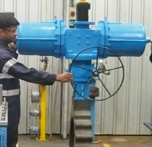
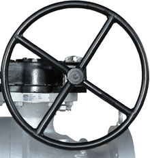
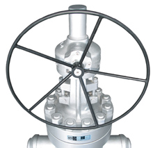
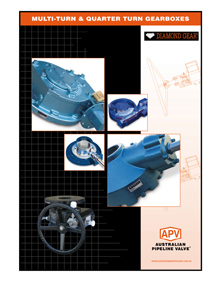
MANUAL OVER-RIDE
Any mechanical device by which an automated valve may be manually operated. On smaller actuators, this may simply be wrench flats on the output shaft of the actuator. Larger actuators may require a more sophisticated system, such as over-ride gearboxes, manual gears, jack screws, or hydraulic hand pump over-ride.
Note - APV-Diamond Gear manufactures manual over-ride gearboxes and Global Supply Line keeps large stocks (see full stock list at GSL website).
At Australian Pipeline Valve (APV) the same knowledge, level of detail and effort we put into this website goes into every product we sell.
If this website helps you, please reward APV with your business!
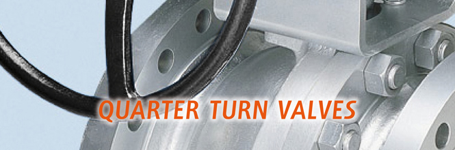
Actuator Sizing Factors Floating Ball Valves
Actuator Sizing Calculation Gate & Globe Valves
Torque and Sizing API600 Gate & Globe Valves
Formulae & Conversions Quarter Turn Worm Gear Boxes
Formulae & Coefficients Gate, Globe & Check Valves